
Next step is to configuring for your Tap configuration.
Here are the steps to take to make your Raspberry Pi work as a Tap controller:
1. Preparing Raspberry Pi
2. Testing the TapHat / Pi connection – Arduino side
3. Testing the TapHat / Pi connection – Pi side
4. Connecting your Hardware
5. Configuring your TapHat and valves
6. Tap Control from the Internet
7. Finishing our Python Tap Control program
Hardware
First we will need to look at the hardware.
[Image needed]
I have the setup as you can see above. I therefor needed two TapHat controllers. You could use even more and just give them a unique i2c address.
System Power
The TapHat gets it’s power from the 5V of the Raspberry Pi: we suggest you use a 5V adapter that can at least provide 2.5 – 3A (like the original Pi adapters for the Pi 3).
12V Power
The ball valves that we use are rated for 12V so we needed to have a separate 12V power supply.
This is how you connect it to the Power input (it says Ext. PWR and shows a + and – above the screw clamp).

The left input is the ground lead of the 12V supply. The right input is for the positive +12V connector. The board has some protection and there is also a thermal fuse that will help protecting the 12V hardware.
Warning: Don’t reverse the two wires. Reversing the wires can cause permanent damage to the TapHat. Use a multimeter if you are unsure what lead is what.
Three wire ball valve
Next we can connect the ball valves. I use two types of valves.

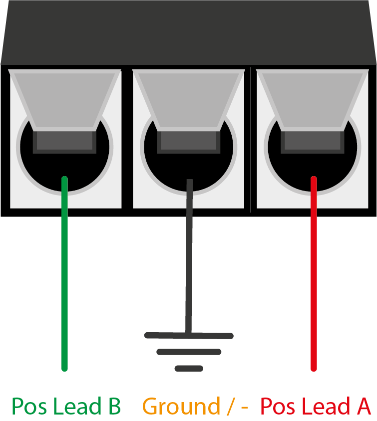
The first type has only three wires. It is a more difficult valve to control compared to normal motors. But this setup also has an advantage: it has internal limit switches: it switches off at it’s extremes (totally closed and totally open). The TapHat has one connector for this type of valve (Tap 3).

There is a common ground and two positives. The TapHat uses two solid state relais to control both ports. Digital pin 5 is connected to the left output (green in the image) and digital pin 6 controls the right (red in the image) output.
Warning: you could potentially enable both sides and that is not good for your valve, so never make D5 and D6 high at the same time. See our example code that uses a special method to make sure you don’t make D5 and D6 high by mistake.
Five wire ball valve
There is also a five wire ball valve. Below you can see a typical schematic for such a ball valve.

Your TapHat has two connectors that are outputs for these ball valves (marked Tap 1 and Tap 2):

The L298D controller chip makes it possible to easily control the outputs of Tap 1 and Tap 2. This chip is often used for controlling DC motors. You could therefore also use the shield to control a small robot.
While some ball valves with five wires also have an automatic off at the limits, my valves did not have that option. The TapHat also has special connectors for the limit sensors:

Sensor port 1 has two connections: A (D15) and B (D16).
Sensor port 2 has two connections: A (D17) and B (D9).
Both sensor ports have so-called full-up resistors connected to both pin A and B. If we read a LOW (0) on A or B we know that we have reached a limit. If we read a HIGH (1) on A / B we know that the switch for A / B is not activated.